UCB CS61C
Info
Study notes based on UCB CS61C, Summer 2020 & Fall 2020 online videos along with its textbooks.
- Abstraction (Layers of Representation/Interpretation)
- Moore's Law
- Principles of Locality/Memory Hierarchy
- Parallelism
- Performance Measurement & Improvement
- Dependability via Redundancy
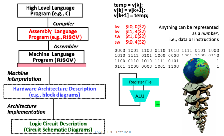
Great Idea #1: Levels of Representation & Interpretation
Number Representation
- Number Bases
We use \(d\times Base^i\) to represent a number, and in computer the \(Base=2\) . Thus, we can also use bits to represent numbers in computer. - Signed Representations
- Sign and Magnitude
- Biased Notation
- One's Complement
- Two's Complement
- Overflow
- most significant bit (MSB): the leftmost bit
- least significant bit (LSB): the rightmost bit
- overflow: the proper result cannot be represented by the hardware bits
- Sign Extension
- Sign and Magnitude: fill with 0's
- One/Two's Complement: fill with MSB
Sidenote
The RISC-V word is 32 bits long.
Quick computation for \(-x\): \(x+\bar{x}=-1\) .
Foundation of complement method:
Consider subtracting a large number from a small one, the answer is that it would try to borrow a string of leading 0s, so the result would have a string of 1s.
This gives us the idea that leading 0s means positive, and leading 1s means negative.
See CS:APP Chapter 2 for more.
High-Level Language Program (e.g. C)
C: Introduction
Basic Concepts
- Compilation
- Comparison
- C: compilers map C programs into architecture-specific machine code
- Java: converts to architecture-independent bytecode (run by JVM)
- Python: directly interprets the code
- Advantage
- Excellent runtime performance: compiler optimizes the code for the given architecture
- Fair compilation time: only modified files need recompilation
- Disadvantage
- Compiled files are architecture-specific
- "Edit \(\to\) Compile \(\to\) Run [repeat]" iteration cycle can be slow
- Comparison
- Variable Types
C Memory Management
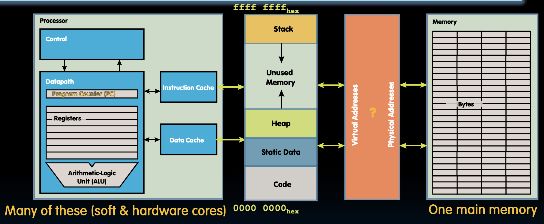
The picture below shows the C memory layout.
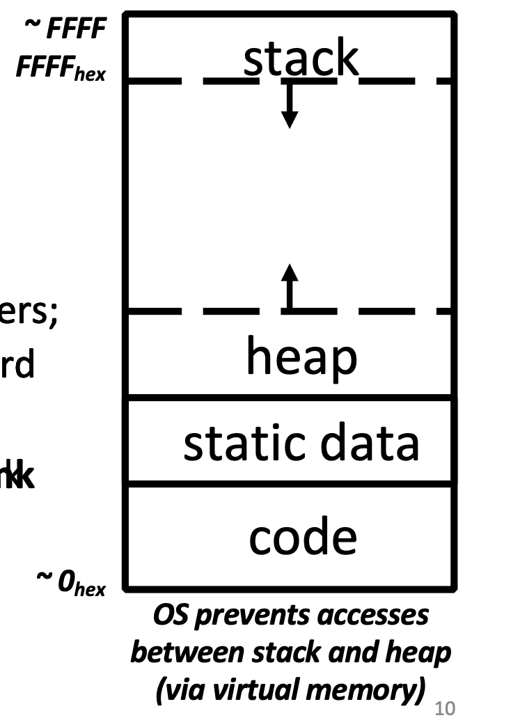
From top to down, we have:
- Stack
- local variables, grows downward
- consists of procedure frames, uses a stack pointer (SP) to tell where the current stack frame is
- Heap
- space requested via
malloc()and used with pointers - resizes dynamically, grows upward
- space requested via
- Static Data
- global and static variables, does not grow or shrink
- string literals \(\in\) static data
char * str = "hi";belongs to, butchar str[] = "hi";does not
- string literals \(\in\) static data
- size does not change, but sometimes data can
- string literals cannot
- global and static variables, does not grow or shrink
- Code
- loaded when program starts, does not change
- typically read only
When it comes to memory management in C, there can be tons of memory problems. For a better understanding of that, refer to CS11L.
Basic Allocation Strategy: K&R Section 8.7
Each continuous spaces allocated by calling malloc() is called a block.
To manage those blocks, we use a linked-list with each node pointing to each block.
When a free() is called, we insert that block into the list and combine it with adjacent blocks.
When a malloc() is called, we first search for the blocks large enough for allocation, then choose one using a method offered below:
- Best-fit: choose the smallest, this provides the least concentrative distribution of small blocks yet a slowest service.
- First-fit: choose the block with least order, this is fast but tends to concentrate small blocks at beginning.
- Next-fit: like first-fit, but resume search from where we last left off. Also fast, and it does not concentrate small blocks at front.
Floating Point
See CS:APP Ch.2 Floating Point.
Single Precision
Use normalized, base 2 scientific representation:

Split a 32-bit word into 3 fields:

Here, we use biased notation (\(bias=-127\)) for the exponent in order to preserve the linearity of value as well as represent a small number.
Double Precision

Everything stays the same as Single Precision except the length of each field.
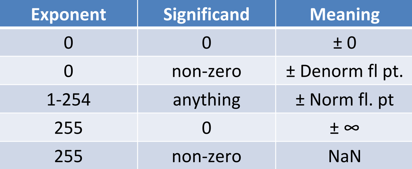
Special Cases
Limitations
- Overflow & Underflow
- Rounding occurs when result runs out of the end of the Significant
- FP addition is not associative due to rounding errors
- As a result, parallel execution strategies that work for integer data may not work for FP
- FP cannot represent all integers
Assembly Language Program (e.g. RISC-V)
RISC-V: Introduction
- Mainstream Instruction Set Architecture: x86, ARM architectures, RISC-V
- Complex/Reduced Instruction Set Computing:
- Early trend: CISC
- difficult to learn
- less work for the compiler
- complicated hardware runs more slowly
- Later began to dominate: RISC
- easier to build fast hardware
- let software do the complicated operations by composing simpler ones
- Early trend: CISC
Assembly Language
- RISC Design Principles: smaller is faster, keep it simple.
- RISC-V Registers:
s0-s11,t0-t6,x0 - RISC-V Instructions
- Arithmetic:
add,sub,addi - Data Tansfer:
lw,sw- Memory is byte-addressed
- Control Flow:
beq,bne,j - Six Steps of Calling a Function
- Place arguments
- Jump to funciton
- Create local storage (Prologue)
- Perform desired task
- Place return value and clean up storage (Epilogue)
- Jump back to caller
- Calling Conventions
- Caller-saved registers (Volatile Registers)
- Callee-saved registers (Saved Registers)
- Arithmetic:
- RISC-V Instruction Formats
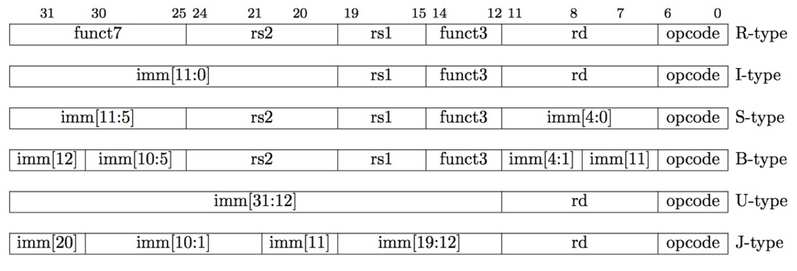
- The Stored Program concept is very powerful.
Machine Language Program (RISC-V)
Translation vs. Interpretation
Interpreter: Directly executes a program in the source language.
Translator: Converts a program from the source language to an equivalent program in another language.
Translation vs. Interpretation:
- Interpreter is slower, but code is smaller
- Interpretor provides instruction set independence
- Translated/compiled code almost always more efficient and therefore higher performance
- Translation/compilation helps "hide" the program "source" from the users
Translation
C translation steps are as follows:
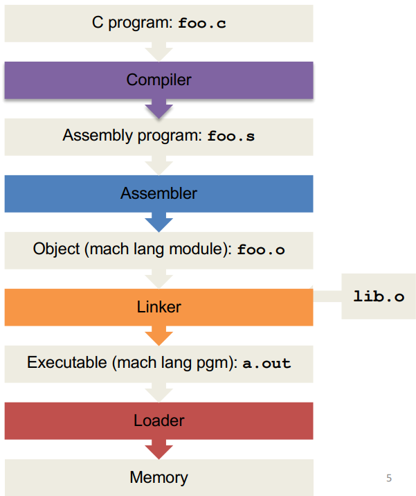
Compiler
- Input: Higher-level language (HLL) code
- Output: Assembly language code (may contain pseudo-instructions)
Assembler
- Input: Assembly language code
- Output: Object code, information tables \(\rightarrow\) Object file
Assembler does this in three steps:
- Reads and uses directives
- Assembly directives: give directions to assembler, but do not produce machine instructions. (
.text,.data,.global sym, etc)
- Assembly directives: give directions to assembler, but do not produce machine instructions. (
- Replaces pseudo-instructions (
mv,li, etc) - Produces machine language
- "Forward Reference" problem
To solve "Forward Reference" problem, we make two passes over the program.
- Pass 1:
- Expands pseudo instructions
- Remember positions of labels
- Take out comments, empty lines, etc
- Error checking
- Pass 2:
- Use label positions to generate relative addresses
- Outputs the object file
For jumps to external labels and references to data, assembler cannot determine yet, but it will create two tables for linker to solve that.
- Symbol Table
- List of "items" that may be used by other files
- Includes labels and data
- Relocation Table
- List of "items" this file will need the address of later (currently undetermined)
- Includes:
- Any external label jumped to
jalorjalr - Any piece of data
- Any external label jumped to
The object file format is listed below from top to down:
- object file header
- text segment
- data segment
- relocation table
- symbol table
- debugging information
Linker
- Input: Object code files, information tables
- Output: Executable code
There are three steps for the linker:
- Place code and data modules symbolically in memory
- Determine the addresses of data and instruction labels
- Patch both the internal and external references
Note that the linker enables separate compilation of files, which saves a lot of compile-time.
Info
The text segment starts at address 0000 0000 0040 0000hex and the data segment at 0000 0000 1000 0000hex.
Three types of addresses:
- PC-Relative Addressing (
beq,bne,jal) \(\rightarrow\) never relocate - External Function Reference (usually
jal) \(\rightarrow\) always relocate - Static Data Reference (often
auipcandaddi) \(\rightarrow\) always relocatelw,swto variables in static area, relative to global pointer
Loader
- Input: Executable code
- Output: \<program is run>
The loader follows these steps:
- Reads executable file's header to determine size of text and data segments
- Creates an address space large enough for text and data
- Copies the instructions and data from executable file into memory
- Copies arguments passed to the program onto the stack
- Initialize machine registers
- Jumps to start-up routine that copies program's arguments from stack to registers and sets the PC
Quote
Virtually every problem in computer science can be solved by another level of indirection.
David Wheeler
Great Idea #2: Moore's Law
Logic Circuit Description
Synchronous Digital Systems (SDS):
- Synchronous
- All operations coordinated by a central clock
- Digital
- Represent all values with two discrete values: 0/1, high/low, true/false
Switches and Transistors
- Switches
- The basic elements of physical implementations
- Transistors \(\rightarrow\) hardware switches
- Modern digital systems designed in CMOS
- MOS transistors acts as voltage-controlled switches
CMOS Networks

- In a word,
- high voltage \(\rightarrow\) N-channel ON, P-channel OFF
- low voltage \(\rightarrow\) N-channel OFF, P-channel ON
- VGS = VGate - VSource; VSG = VSource - VGate; VTH = VThreshold
In abstraction, we can simply view chips composed of transistors and wires as block diagrams.
Combinational Digital Logic
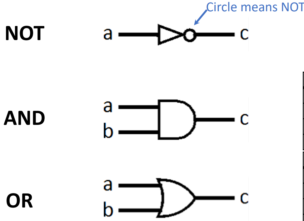
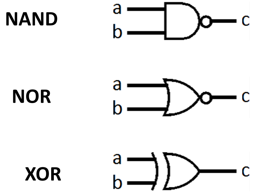
Combinational Logic Gates
Digital Systems consists of two basic types of circuits:
- Combinational Logic (CL) e.g. ALUs
- Sequential Logic (SL) e.g. Registers
Boolean Algebra
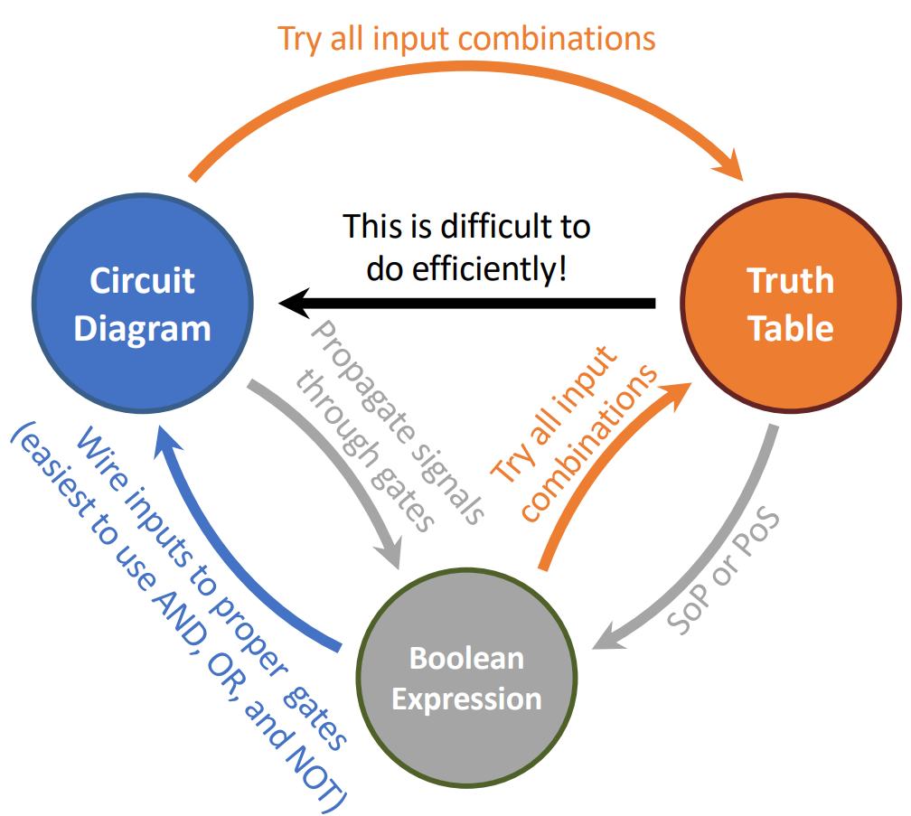
Translate truth table to boolean algebra:
- Sum of Products (SoP)
- Product of Sums (PoS)
Circuit Simplification
Hardware can have delays, so we should simplify boolean expressions \(\rightarrow\) smaller transistor networks \(\rightarrow\) smaller circuit delays \(\rightarrow\) faster hardware.
Summary
Sequential Digital Logic
In combinational digital logic, systems are memoryless. However, when we want to sum up a series of numbers without knowing its length, this is impossible to implement with memoryless circuits. Thus, we now introduce registers.
Register Details

Inside a register are a number of flip-flops (FFs). Here we're talking about the most common type of flip-flops, called an edge-triggered d-type flip-flop.
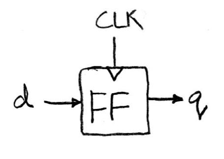
Take a look at a single FF, here d is referred as input and q as output.
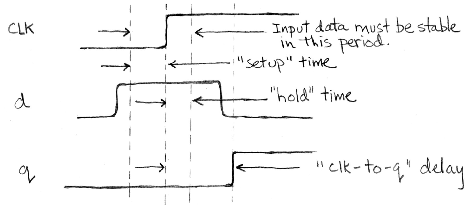
On the rising edge of the clock, the input d is sampled and transferred to the output q. At other times, d is simply ignored.
When a FF feels that there is a change at the input side, it knows that it maybe time to change. However, just like combinational logic circuits, FF cannot change its value instantaneously. Also, time is needed to transfer inputs internally. The combination of these (the former one called setup time, and the latter called hold time) two create a time window when the input d cannot change. Also, after the FF has successfully captured the new input, it takes a small amount of time to transfer that to the output. This delay is called clk-to-q delay.
Pipelining--Adding Registers to Improve Performance
Consider the example in the slides, we can infer that the maximum clock frequency is limited by the propagation of the critical path.
To resolve that issue, we can employ the technique called pipelining. In details, that means to add more registers. Notably that this will cause a signal passing through the same path (ignore the added registers) with more cycles (while the length of a cycle is shrunk), but in the long run, it actually improves performance.
Finite State Machines
To represent sequential logic, finite state machines are a good idea. Correspondingly, with combinational logic and registers, any FSM can be implemented in hardware.
Functional Units (a.k.a. Execution Unit)
Take a look at the examples in the slides.
Hardware Architecture Description
CPU
Datapath and Control
A CPU involves two parts:
- Datapath: contains the hardware necessary to perform operations required by the processor
- Control: decides what each piece of datapath should do
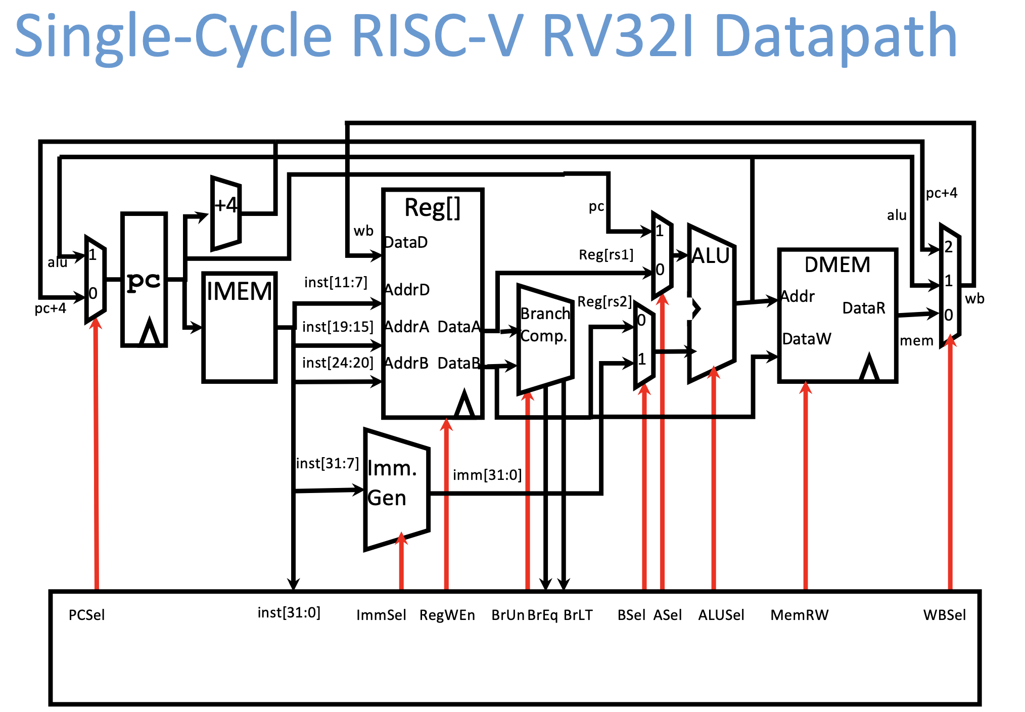
The picture above shows the basic architecture of a single-cycle RISC-V RV32I datapath.
Single Cycle CPU: All stages of an instruction completed within one long clock cycle.

Processor design principles:
- Five steps:
- Analyze instruction set \(\rightarrow\) datapath requirements
- Select set of datapath components & establish clock methodology
- Assemble datapath meeting the requirements
- Analyze implementation of each instruction to determine setting of control points that effects the register transfer
- Assemble the control logic
- Formulate Logic Equations
- Design Circuits
- Determining control signs
Control construction options:
- ROM
- Can be easily reprogrammed
- Popular when design control logic manually
- Combinatorial Logic
- Not easily re-programmable because requires modifying hardware
- Likely less expensive, more complex
Great Idea #3: Principle of Locality
Caches
Principle of Locality: Programs access only a small portion of the full address space at any instant time
- Temporary Locality (time)
- Spatial Locality (space)
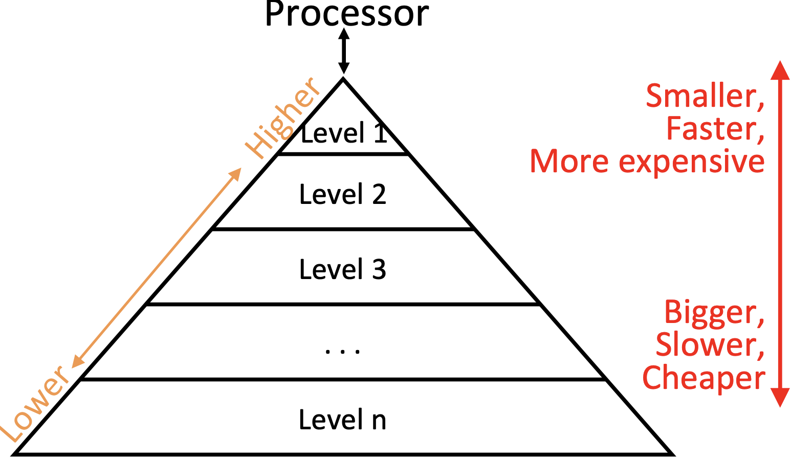
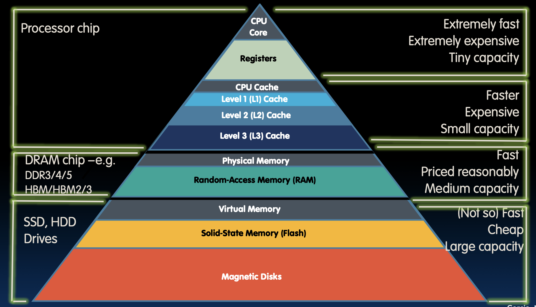
In typical memory hierarchy, from top to down we have:
- RegFile
- First Level Cache (consists of Instr Cache & Data Cache) \(\rightarrow\)
$L1 - Second Level Cache (SRAM) \(\rightarrow\)
$L2 - Main Memory (DRAM)
- Secondary Memory (Disk or Flash)
Upper above the Main Memory are On-Chip Components.
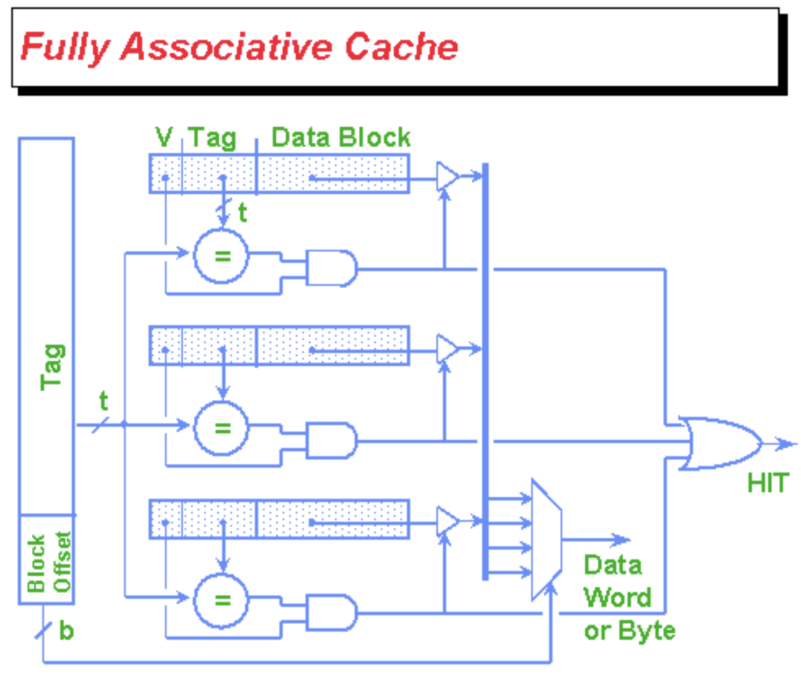
Fully Associative Caches
Fully associative: each memory block can map anywhere in the cache.

In the cache:
- Each cache slot contains the actual data block (\(8\times 2^{\mathrm{Offset}}\) bits)
Tagfield as identifier (\(\mathrm{Tag}\) bits)Validbit indicate whether cache slot was filled in (\(1\) bit)- Any necessary replacement management bits ("LRU(Least Recently Used) bits" - variable \(\#\) bits)
Total bits in cache = \(\#\, \mathrm{slots}\times(8\times 2^{\mathrm{Offset}}+\mathrm{Tag}+1+?)\) bits
Direct-Mapped Caches
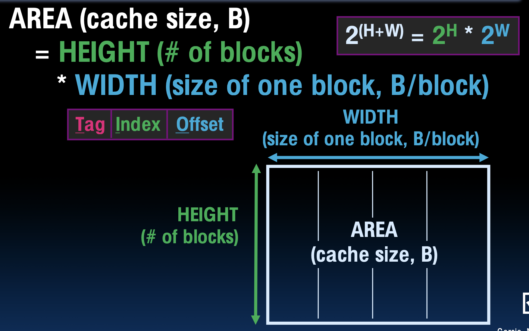
Direct-mapped cache: each memory address is associated with one possible block within the cache
Within the cache:
- Index: which row/block
- \(\# \mathrm{blocks}/ \mathrm{cache}=\dfrac{\mathrm{bytes/ cache}}{\mathrm{bytes/ block}}\)
- Offset: which byte within the block
- Tag: distinguish between all the memory addresses that map to the same location
- \(\mathrm{tag \, length=addr \, length - offset - index}\)
N-Way Set Associative Caches
pros:
- avoids a lot of conflict misses
- hardware cost isn't that bad: only need N comparators
1-way set assoc \(\leftarrow\) directly mapped
M-way set assoc \(\leftarrow\) fully assoc
Writes, Block Sizes, Misses
- Effective
- Hit rate (HR)
- Miss rate (MR)
- Fast
- Hit time (HT)
- Miss penalty (MP)
Handle cache hits:
- Read hits (
I$&D$)- Fasted possible scenario
- Write hits (
D$)- Write-Through Policy: always write to cache and memory (through cache)
- Write buffer
- Write-Back Policy: write only to cache, update memory when block is removed
- Dirty bit
- Write-Through Policy: always write to cache and memory (through cache)
Handle cache misses:
- Read misses (
$I&$D)- Stall, fetch from memory, put in cache
- Write misses (
$D)- Write Allocate Policy: bring the block into the cache after a write miss
- No Write Allocate Polity: only change main memory
- Write allocate \(\leftrightarrow\) write back, every slot needs an extra
dirtybit - No write allocate \(\leftrightarrow\) write-through
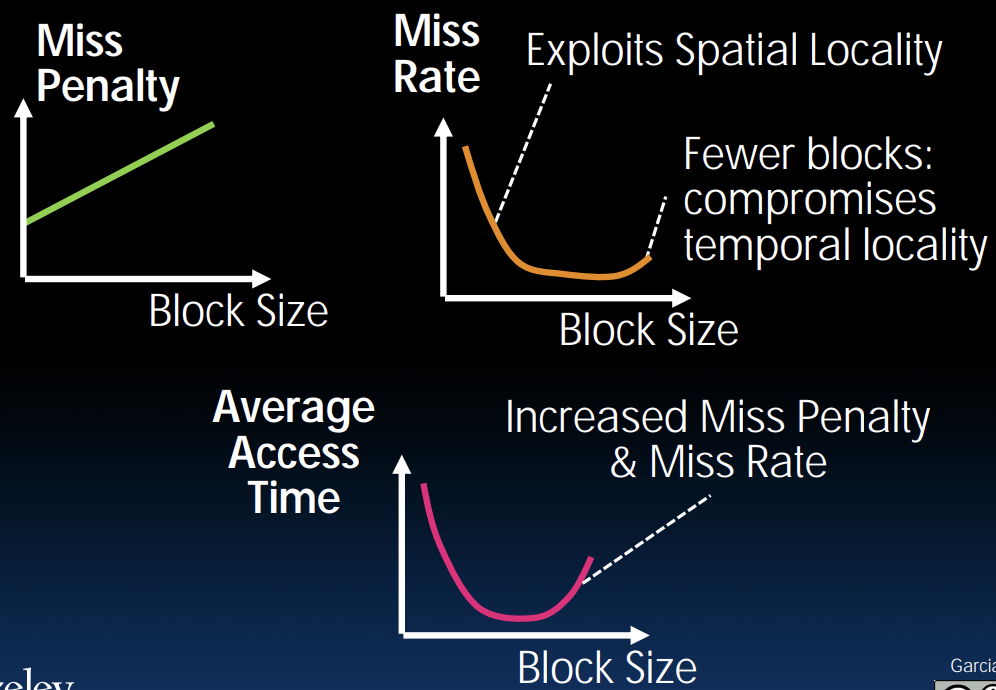
Block size tradeoff:
- Benefits of larger block size
- Spatial Locality
- Very applicable with Stored-Program Concept
- Works well for sequential array accesses
- Drawbacks of larger block size
- Larger miss penalty
- If block size is too big relative to cache size, then there are too few blocks \(\rightarrow\) Higher miss rate
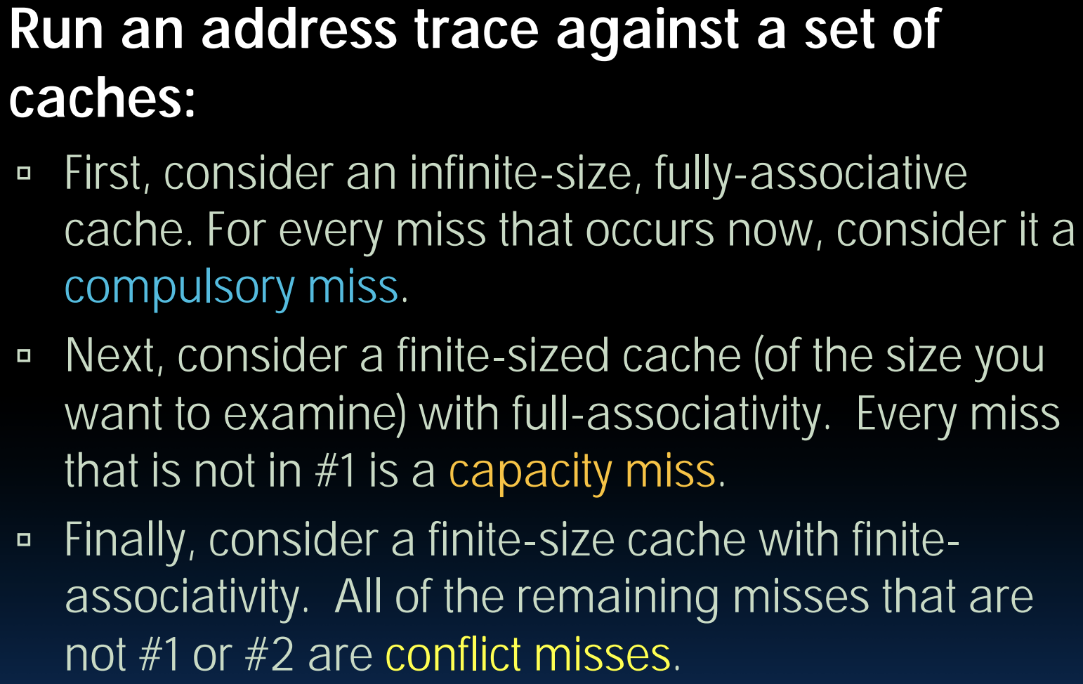
Types of cache misses:
- Compulsory Misses
- Conflict Misses (Direct-Mapped Cache only)
- Solution 1: Make the cache size bigger
- Solution 2: Multiple distinct blocks can fit in the same cache Index
- Capacity Misses (primary for Fully Associative Cache)
How to categorize misses:
Block Replacement Policy
- LRU (Least Recently Used)
- FIFO
- Random
Average Memory Access Time
AMAT = Hit Time \(+\) Miss Penalty \(\times\) Miss Rate
Abstract
Why not "Hit Time \(\times\) Hit Rate \(+\) Miss Time \(\times\) Miss Rate"?
AMAT = Hit Time \(\times\) (1 \(-\) Miss Rate) + (Miss Penalty \(-\) Hit Time) \(\times\) Miss Rate
Abstract
Big Idea: If something is expensive but we want to do it repeatedly, do it once and cache the result
Cache Design Choices:
- size of cache: speed vs. capacity
- block size
- write policy
- associativity choice of N
- block replacement policy
- 2nd level cache
- 3rd level cache
OS
Basics
What does OS do?
- OS is the first thing that runs when computer starts
- Finds and controls all devices in the machine in a general way
- Starts services
- Loads, runs and manages programs
What does the core of OS do?
- Provides isolation between running processes
- Provides interaction with the outside world
What does OS need from hardware?
- Memory translation
- Protection and privilege
- Split the processor into at least two modes: "User" and "Supervisor"
- Lesser privilege cannot change its memory mapping
- Traps & Interrupts
- A way of going into supervisor mode on demand
What happens at boot?
- BIOS1: Find a storage device and loads the first sector
- Bootloader: Load the OS kernel from disk into a location in memory and jump into it
- Init: Launch an application that waits for input in loop (e.g., Terminal/Desktop/...)
- OS Boot: Initialize services, drivers, etc.
OS Functions
Refer to the lecture slides.
Virtual Memory
- Processes uses virtual addresses
- Memory uses physical addresses
Address space = set of addresses for all available memory locations.
Responsibilities of memory manager:
- Map virtual to physical addresses
- Protection: isolate memory between processes
- Swap memory to disk: give illusions of larger memory by storing some contents on disk
Physical memory (DRAM) is broken into pages:

Paged memory translation:
- OS keeps track of active processes
- Memory manager extracts page number from virtual address
- Looks up page address in page table
- Computes physical memory address from sum of
- page address and
- offset (from virtual address)
Note
Physical addresses may have more or fewer bits than virtual addresses.
Since a page table is too large for a cache, so we have to store it in memory (DRAM, acts like caches for disk). To minimize performance penalty, we can:
- Transfer blocks (not words) between DRAM and caches
- Use a cache for frequently accessed page table entries
Refer to slides.
I/O
Interface options:
- Special I/O instructions
- Memory mapped I/O
- Use normal load/store instructions
I/O polling:
- Device registers:
- Control register
- Data register
- Processor reads from control register in loop
- then loads from (input) / writes to (output) data register
- Procedure called "polling"
Polling wastes processor resources, there is an alternative called "interrupts":
- No I/O activity: nothing to do
- Lots of I/O: expensive - thrashing cashes, VM, saving/restoring state
When there is low data rate, we use interrputs. While there's high data rate, we start with interrupts, then switch to Direct Memory Access (DMA).
The DMA allows I/O devices to directly read/write main memory, introducing a new hardware called DMA engine to let CPU execute other instructions.
- Incoming data
- Receive interrupt from device
- CPU takes interrupt, initiates transfer
- Device/DMA engine handle the transfer
- CPU is free to execute other things
- Upon completion, device/DMA engine interrupts the CPU again
- Outging data
- CPU decides to initiate transfer, confirms that external device is ready
- CPU begins transfer
- Device/DMA engine handle the transfer
- Device/DMA engine interrupt the CPU again to signal completion
To plug in the DMA engine in the memory hierarchy, there are two extremes:
- Between
L1$and CPU- Pro: free coherency
- Con: trash the CPU's working set with transferred data
- Between Last-level cache and main memory
- Pro: don't mess with cache
- Con: need to explicitly manage coherency
Great Idea #4: Parallelism
Pipelining
Intro
Noticing that since we have to set the maximum clock frequency to the lowest value to fit in lw instruction, there will always be chips idle when performing other instructions.
As an analogy to doing laundry, we can use pipelining to increase throughput of entire workload.
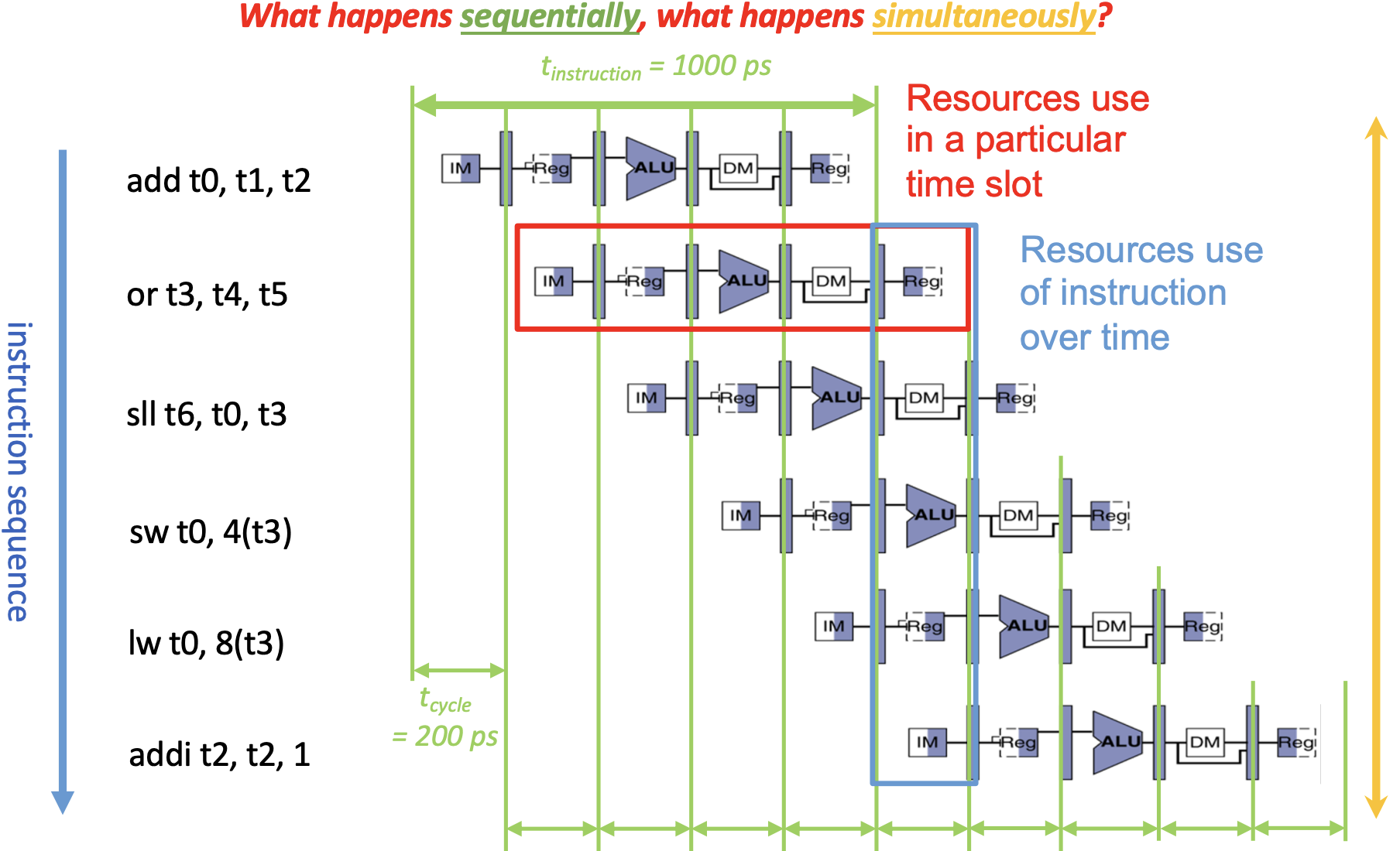
To align the five instruction stages, we place a register between each two stages as a buffer.
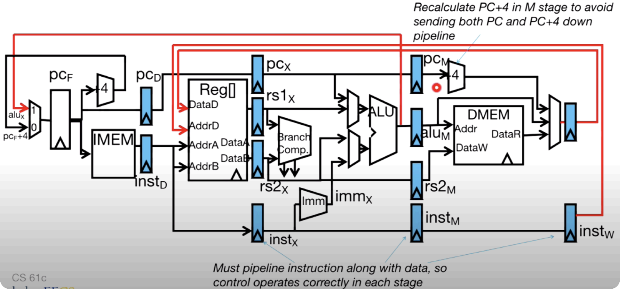
Hazards
With pipelining, we successfully improve single cycle performance, however, this also leads to some problems which is called hazard.
A hazard is a situation that prevents starting the next instruction in the next clock cycle.
- Structural hazard: a required resource is busy
- Solution 1: stalling
- Solution 2: add more hardware
- Can always solve a structural hazard by adding more hardware
- Regfile Structural Hazards
- Solution 1: build Regfile with independent read and write ports
- Solution 2: double pumping
- Read and Write during same clock cycle is okay (write first, then read)
- Memory Structural Hazards
- Solution: build memory with separate instruction/data units/caches
- RISC ISAs designed to avoid such hazards
- Data hazard: data dependency between instructions
- R-type instructions
- Solution 1: stalling
- Solution 2: forwarding (a.k.a bypassing)
- Load instructions
- Solution 1: stalling =
nop - Solution 2: let the compiler/assembler put an unrelated instruction in that slot (slot after a load is called a load delay slot)
- Solution 1: stalling =
- R-type instructions
- Control hazard: flow of execution depends on previous instruction
- Solution 1: stalling
- Solution 2: move branch comparator to ID stage
- Solution 3: branch prediction - guess outcome of a branch, fix afterwards if necessary
Parallelism
Flynn's Taxonomy
- Choice of hardware and software parallelism are independent
- Flynn's Taxonomy is for parallel hardware

Instruction-Level
To improve performance, Intel's SIMD instructions:
- Fetch one instruction, do the work of multiple instructions
- MMX (MultiMedia eXtension)
- SSE (Streaming SIMD Extension)
In the evolution of x86 SIMD, it started with MMX, getting new instructions, new and wider registers, more parallelism.
In SSE, architecture extended with eight 128-bit data registers, which are called XMM registers.
Note
In 64-bit address architecture, they are available as 16 64-bit registers.
Programming in C, we can use Intel SSE intrinsics, which are C functions and procedures for putting in assembly language, including SSE instructions.
| Operations | Intrinsics | Corresponding SSE instructions |
|---|---|---|
| Vector data type | _m128d |
|
| Load and store operations | _mm_load_pd_mm_store_pd |
MOVAPD/aligned, packed doubleMOVAPD/aligned, packed double |
| Arithmetic | _mm_add_pd_mm_mul_pd |
ADDPD/add, packed doubleMULPD/multiple, packed double |
2x2 Matrix Multiply
#include <stdio.h>
// header file for SSE compiler intrinsics
#include <emmintrin.h>

// NOTE: vector registers will be represented in comments as v1 = [a | b]
// where v1 is a variable of type __m128d and a, b are doubles

int main(void) {
    // allocate A,B,C aligned on 16-byte boundaries
    double A[4] __attribute__ ((aligned (16)));
    double B[4] __attribute__ ((aligned (16)));
    double C[4] __attribute__ ((aligned (16)));
    int lda = 2;
    int i = 0;
    // declare several 128-bit vector variables
    __m128d c1,c2,a,b1,b2;

    // Initialize A, B, C for example
    /* A = (note column order!)
       1 0
       0 1
    */
    A[0] = 1.0; A[1] = 0.0; A[2] = 0.0; A[3] = 1.0;

    /* B = (note column order!)
       1 3
       2 4
    */
    B[0] = 1.0; B[1] = 2.0; B[2] = 3.0; B[3] = 4.0;

    /* C = (note column order!)
       0 0
       0 0
    */
    C[0] = 0.0; C[1] = 0.0; C[2] = 0.0; C[3] = 0.0;

    // used aligned loads to set
    // c1 = [c_11 | c_21]
    c1 = _mm_load_pd(C+0*lda);
    // c2 = [c_12 | c_22]
    c2 = _mm_load_pd(C+1*lda);

    for (i = 0; i < 2; i++) {
        /* a =
        i = 0: [a_11 | a_21]
        i = 1: [a_12 | a_22]
        */
        a = _mm_load_pd(A+i*lda);
        /* b1 =
        i = 0: [b_11 | b_11]
        i = 1: [b_21 | b_21]
        */
        b1 = _mm_load1_pd(B+i+0*lda);
        /* b2 =
        i = 0: [b_12 | b_12]
        i = 1: [b_22 | b_22]
        */
        b2 = _mm_load1_pd(B+i+1*lda);
        /* c1 =
        i = 0: [c_11 + a_11*b_11 | c_21 + a_21*b_11]
        i = 1: [c_11 + a_21*b_21 | c_21 + a_22*b_21]
        */
        c1 = _mm_add_pd(c1,_mm_mul_pd(a,b1));
        /* c2 =
        i = 0: [c_12 + a_11*b_12 | c_22 + a_21*b_12]
        i = 1: [c_12 + a_21*b_22 | c_22 + a_22*b_22]
        */
        c2 = _mm_add_pd(c2,_mm_mul_pd(a,b2));
    }

    // store c1,c2 back into C for completion
    _mm_store_pd(C+0*lda,c1);
    _mm_store_pd(C+1*lda,c2);

    // print C
    printf("%g,%g\n%g,%g\n",C[0],C[2],C[1],C[3]);
    return 0;
}
To improve RISC-V performance, add SIMD instructions (and hardware) – V extension:
vadd vd, vs1, vs2
Thread-Level
Multicore
Multiprocessor execution model:
- Each processor (core) executes its own instructions
- Separate resources:
- datapath
- highest level caches
- Shared resources:
- memory (DRAM)
- Advantages:
- simplifies communication in program via shared variables
- Drawbacks:
- does not scale well
- "slow" memory shared by too many "customers" (cores)
- may become bottleneck
- does not scale well
- Advantages:
- often 3rd level cache
- memory (DRAM)
- Nomenclature:
- "multiprocessor microprocessor"
- multicore processor
Thread
- Thread: "thread of execution", is a single stream of instructions.
- With a single core, a single CPU can execute many threads by time sharing.
- Each thread has:
- dedicated program counter
- separate registers
- accesses the shared memory
- Each physical core provides one:
- hardware threads that actively execute instructions
- each executes one "hardware instructions"
- OS multiplexes multiple:
- software threads onto the available hardware threads
- all threads except those mapped to hardware threads are waiting
Multithreading
When an active thread encounters cache miss, we switch out to execute another thread. However, saving the current state and loading the new state can be expensive. As a result, we consider asking hardware for help. And Moore's Law tells us that transistors are plenty.
Then, we came up with hardware assisted software multithreading. We simply make two copies of PC and registers inside processor hardware, this makes it looks identical to two processors. Thus we now have hyper-threading (aka simultaneously multithreading, SMT), which means that both threads can be active simultaneously.
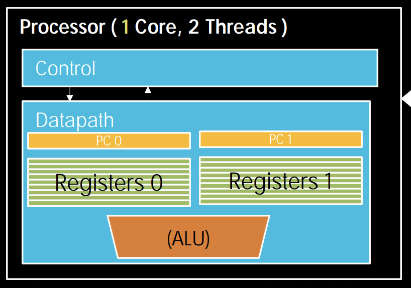
PS: MIMD is thread-level parallelism, while SIM is instruction-level.
OpenMP's Fork-Join Model:
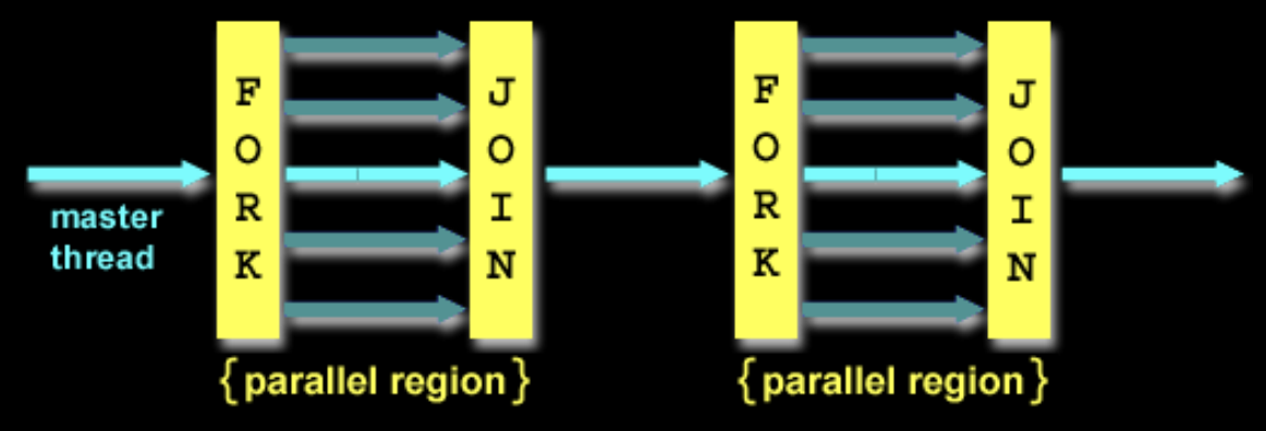
Note that OpenMP threads are operating system (software) threads, and OS will multiplex requested OpenMP threads onto available hardware threads. Hopefully each gets a real hardware thread to run on, so there will be no OS-level time-multiplexing. However, others tasks will compete for hardware threads, so be careful when timing result for projects.
Synchronization
To solve the problem that different threads could be "racing" for shared resources which will lead to a nondeterministic result, computers use locks to control access, which relies on hardware synchronization instructions.
- Solution: Atomic read/write
- R-Type instruction format:
Add,And, ... 
amoadd.w rd, rs2, (rs1)
- R-Type instruction format:
Deadlock: a system state in which no progress is possible.
- Solution: elapsed wall clock time
Shared Memory and Caches
SMP: (Shared Meomory) Symmetric Multiprocessor
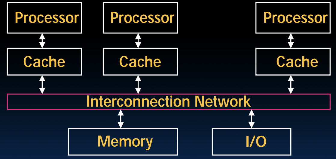
How does hardware keep caches coherent?
- Each cache tracks state of each block in cache:
- Shared: up-to-date data, other caches may have a copy
- Modified: up-to-date data, changed (dirty), no other cache has a copy, OK to write, memory out-of-date (i.e., write back)
- Exclusive: up-to-date data, no other cache has a copy, OK to write, memory up-to-date
- Owner: up-to-date data, other caches may have a copy (they must be in Shared state)
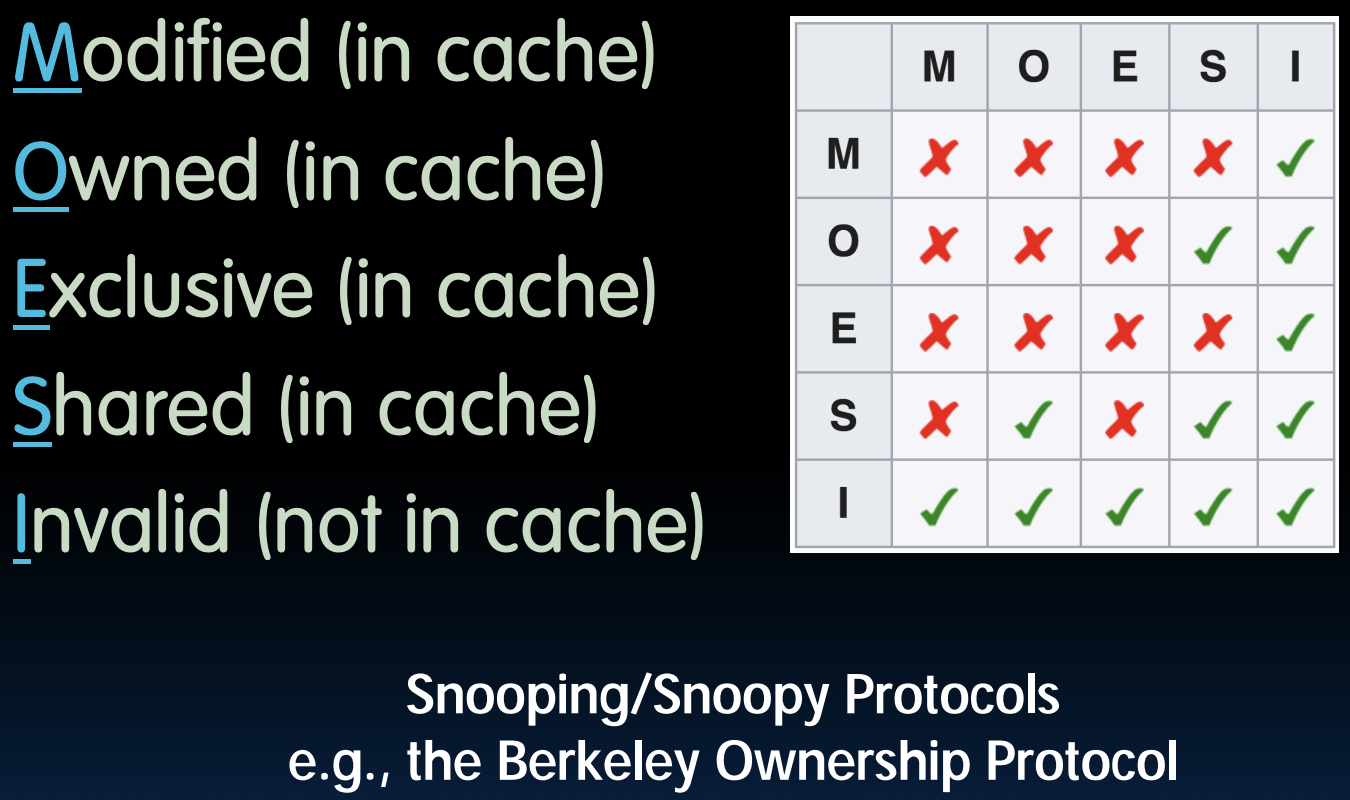
Coherency Tracked by Cache Block:
- false sharing: block ping-pongs between two caches even though processors are accessing disjoint variables
- 4th "C" of cache misses: Coherence Misses
Request-Level
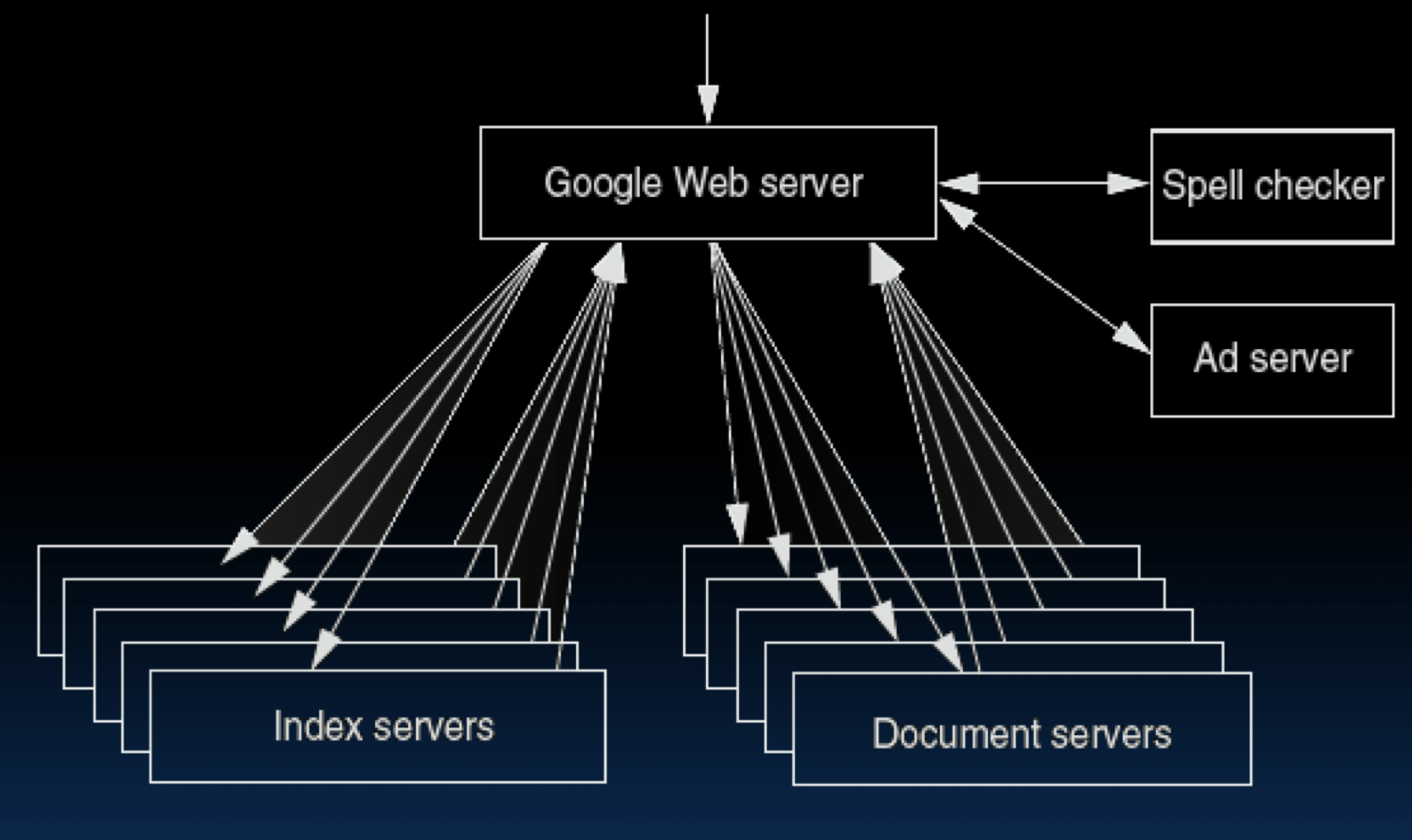
Google query-serving architecture:
Data-Level
Two kinds:
- Data in memory
- Data on many disks
MapReduce
Design goals:
- Scalability to large data volumes
- Cost-efficiency
- Simplified data processing on large clusters
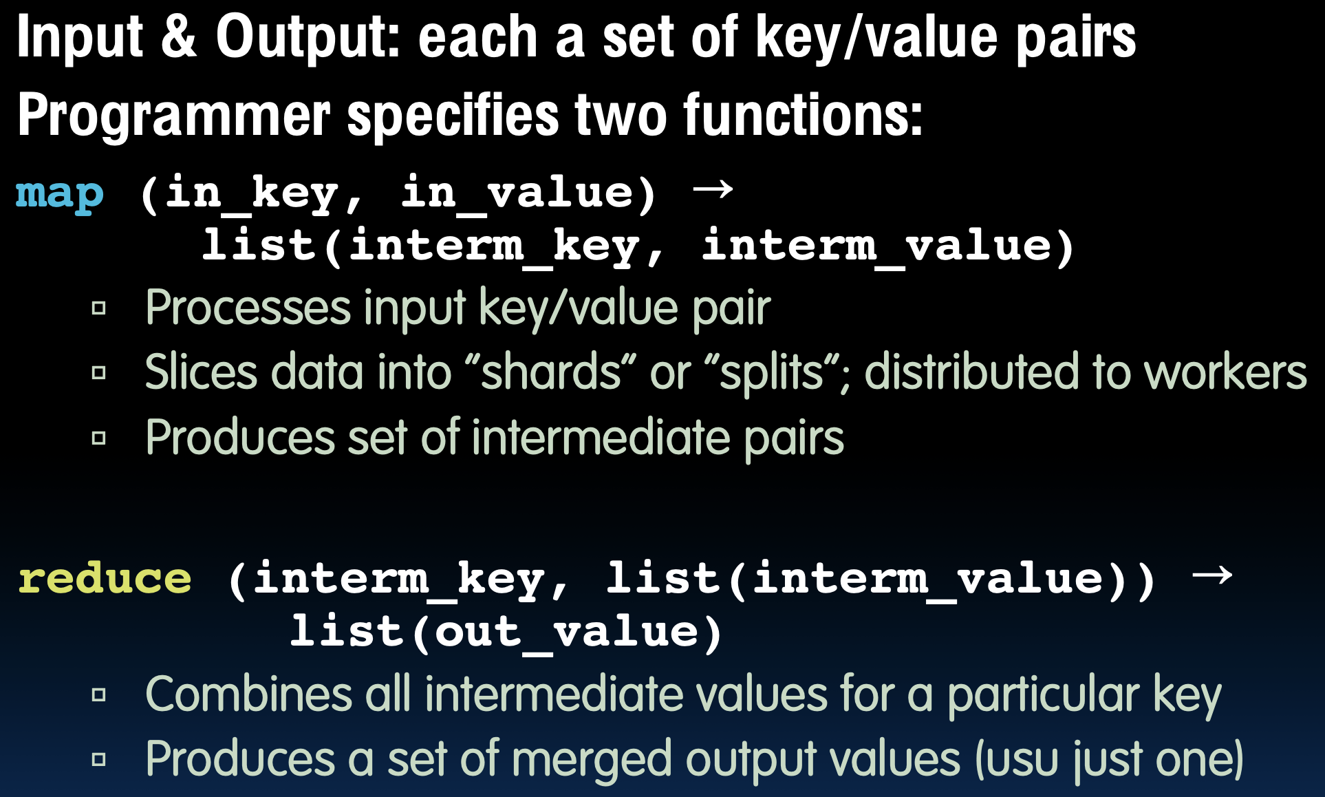
MapReduce is centralized:
- Master assigns map + reduce tasks to "worker" servers
- As soon as a map task finishes, worker server can be a new map or reduce task
- To tolerate faults, reassign task if a worker server "dies"
In conclusion, MapReduce is a wonderful abstraction for programming thousands of machines. It hides details of machine failures, and it is file-based.
Spark
Apache's Spark is a fast and general engine for large-scale data processing.
It is better than MapReduce. It combines the techniques of lazy-evaluation along with memory-based data processing.
Great Idea #5: Performance Measurement & Improvement
CPU Performance Analysis
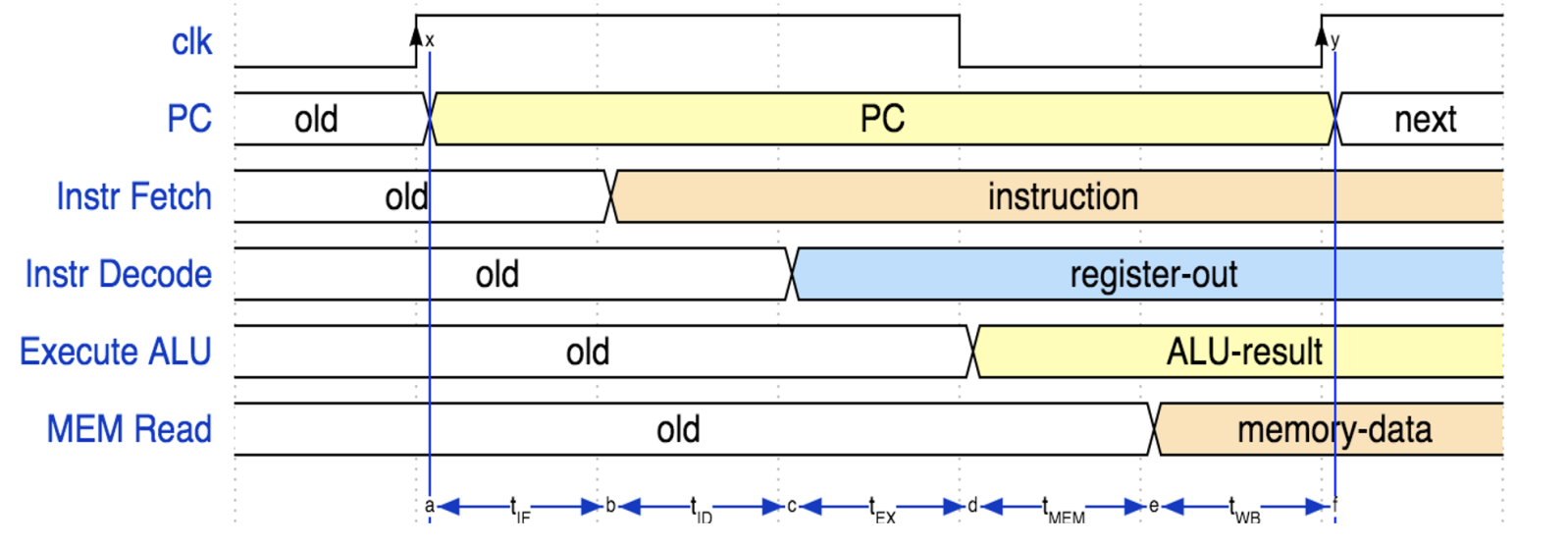
lw instruction needs to do all the things, so it is the bottleneck of a single cycle.
"Iron law" of processor performance:
Amdahl's Law
- Speed up due to enhancement \(E\) : \(\text{Speedup w/E}=\dfrac{\text{Exec time w/o E}}{\text{Exec time w/E}}\)
- Example:
- \(E\) does not affect a portion of \(s(s<1)\) of a task
- It does accelerate the remainder \((1-s)\) by a factor \(P(P>1)\)
- \(\text{Exec time w/E}=\text{Exec time w/o E}\times[s+(1-s)/P]\)
- \(\text{Speedup w/E}=1/[s+(1-s)/P]<\dfrac{1}{s}\)
Great Idea #6: Dependability via Redundancy
Refer to slides.
-
BIOS: Basic Input Output System ↩
